

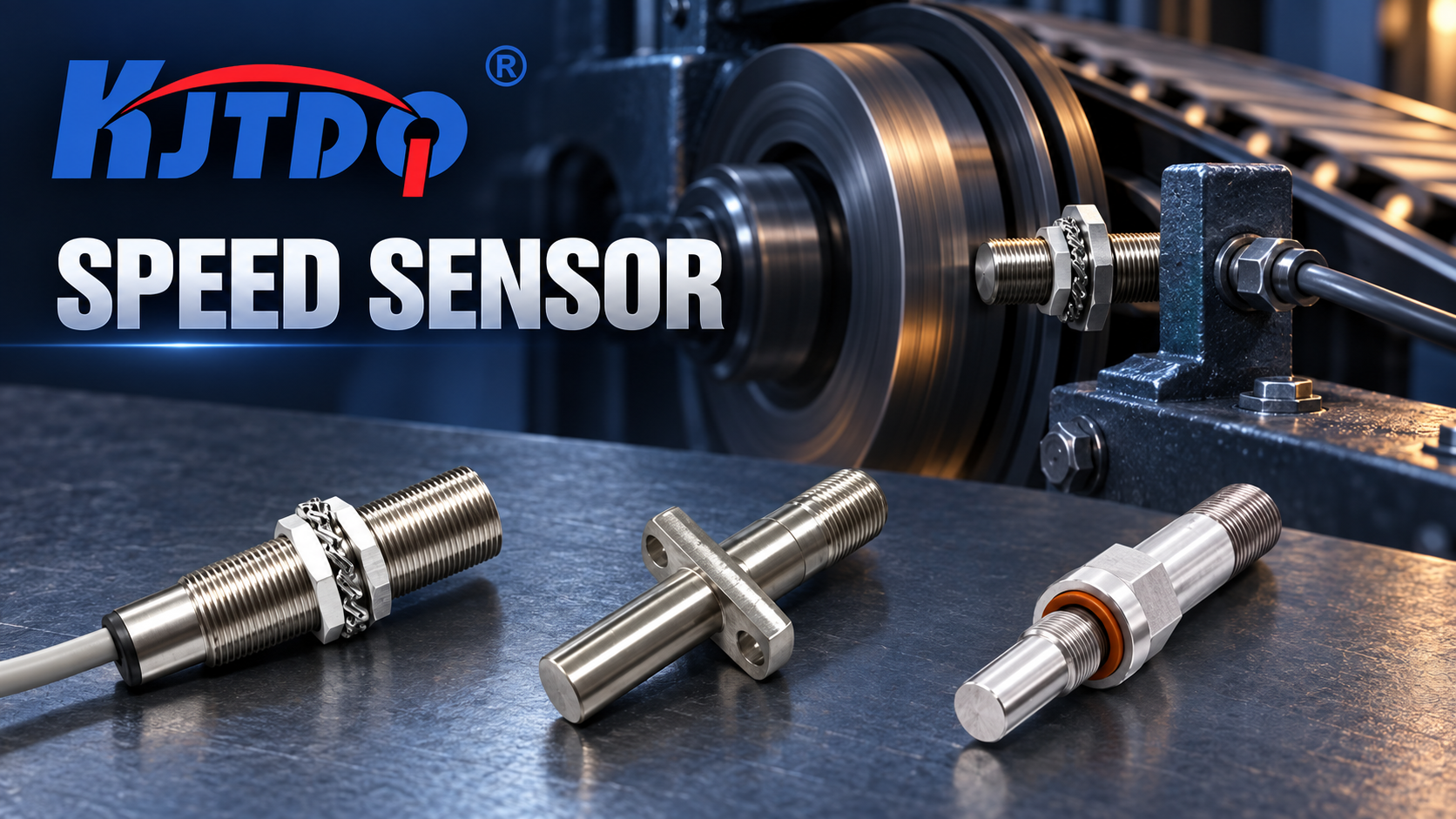
A speed sensor misses pulses when the target signal falls below what the sensor or the input circuit can resolve — excessive air gap, target runout, very low speed, or a pulse frequency beyond the sensor's switching frequency — and adds pulses when vibration makes the target cross the switching threshold repeatedly or electrical noise is counted as signal. The first safe check is dimensional: measure the actual air gap and its variation across one revolution against the data sheet. Signal measurements near rotating parts and VFD wiring belong to qualified personnel; keep hands, tools and loose clothing clear of rotating machinery at all times.
Key Takeaways
- Missed pulses are a margin problem. Gap too large, target too small, speed too low (insufficient signal amplitude on passive pickups), or tooth frequency above the sensor's switching frequency — all shrink the signal margin until teeth are skipped.
- Extra pulses are a threshold or noise problem. Vibration carries the target back and forth across the switching point (double counts per tooth), and VFD/motor-cable noise injected into the signal line is counted as teeth.
- Runout makes the gap a moving target. A bent shaft, eccentric gear or loose hub varies the gap every revolution — the worst point of the revolution decides whether pulses are lost, not the average gap.
- The PLC is part of the count. Input filters, counter-card maximum frequency and scan behavior can drop or merge pulses even when the sensor is perfect — verify the whole chain before condemning the sensor.
- Measure at the extremes. Diagnose at the lowest and highest operating speed, not at a convenient mid-speed; pulse problems live at the edges.
Symptom Definition
This article covers counting errors between the rotating target and the controller:
- Missed pulses — measured speed reads low, drops out at high speed, or reads zero below a threshold speed;
- Extra pulses — measured speed reads high, is erratic, or counts while the shaft is visibly stopped (noise);
- Intermittent count — correct counts interrupted by bursts of loss or excess, typically correlated with vibration or electrical events.
If the pulses are correct but the speed switch or slip logic trips wrongly during conveyor startup, that is a logic/setting topic — covered in the conveyor startup-trip guide (conveyor startup-trip troubleshooting article).
Cause Table
| Cause category | Why it creates the symptom | Safe check | Corrective direction | Technician required? |
|---|---|---|---|---|
| Air gap too large | Signal amplitude falls with distance; beyond the reliable gap, teeth stop crossing the switching threshold | Measure the gap with feeler gauges (machine stopped, locked out); compare with the data-sheet range | Reduce the gap into the specified range; check bracket rigidity | Yes — work near rotating parts, machine stopped |
| Target runout / eccentricity | The gap varies per revolution; misses cluster at the far point, doubles at the near-vibration point | Rotate by hand (locked out) and measure gap at multiple positions; inspect for bent shaft/loose hub | Correct the mechanical runout; set the gap for the worst position with margin | Yes |
| Low speed below pickup capability | Passive (variable-reluctance) pickups generate amplitude proportional to speed — below a threshold the signal is too small to switch | Note the speed at which counting starts/stops; compare with the model's minimum-speed statement | Use an active (Hall/eddy-current) sensor for low and zero speed; the selection guide (https://www.kjt-sensors.com/show-27172.html) maps the principles | Yes for substitution validation |
| Tooth frequency above switching frequency | Teeth per revolution × revolutions per second exceeds the sensor's switching frequency — the sensor merges teeth | Compute the maximum tooth frequency; compare with the model's stated switching frequency (KJT Sensors' gear speed sensor family states ranges up to 0–25 kHz on selected models — verify the exact model) | Reduce teeth count, or select a higher-frequency model | Yes for reselection |
| Vibration at the sensing point | Radial vibration moves the target across the threshold repeatedly per tooth — extra counts; axial vibration varies the gap | Correlate count errors with machine vibration state; inspect mounting stiffness | Stiffen the mounting; correct the vibration source; maintain gap margin | Yes |
| Electrical noise / EMC | VFD and motor cables inject noise into unshielded or parallel-routed signal lines; the input counts noise as pulses | Check cable routing against power cables; note correlation with VFD operation | Separate/shield routing per the manual; grounding per the manual; review input filtering | Yes — electrical work |
| PLC input filtering / counter limits | Input filter time or counter-card maximum frequency drops fast pulses; debounce settings can double-count slow ones | Compare the sensor's output (oscilloscope or counter reading by qualified personnel) with the PLC's count at the same instant | Match filter and counter settings to the computed pulse frequency; the integration guide (https://www.kjt-sensors.com/show-27155.html) covers the chain checks | Yes |
Diagnostic Sequence (Least Invasive First)
- Compute the pulse arithmetic. Teeth per revolution × maximum RPM ÷ 60 = maximum tooth frequency. Compare with the sensor's switching frequency and the counter's maximum input frequency. Arithmetic eliminates two whole cause families in minutes.
- Characterize the error. Missed at high speed (frequency limit), missed at low speed (amplitude limit), extra under vibration (threshold), extra with VFD activity (noise), or count-with-shaft-stopped (pure noise)?
- Measure the air gap and runout. Machine stopped and locked out: gap at several angular positions; set for the worst case per the data sheet.
- Inspect the target. Tooth damage, debris between teeth, wrong replacement gear (different module/tooth count), painted or corroded faces.
- Check mounting stiffness. Bracket deflection under vibration returns as gap modulation.
- Verify the signal chain (qualified personnel). Observe the sensor's raw output with an oscilloscope or counter while the PLC counts in parallel — a mismatch between the two isolates sensor-side from PLC-side.
- Check EMC measures. Shielding, separation from VFD/motor cables, grounding — against the manual and site electrical standards.
- Escalate with data. Persistent errors after gap, target and chain verification: send the target geometry, speed range and signal captures below.
Conditional Corrective Actions
- If counting dies below a certain speed on a passive pickup → switch to an active principle (Hall or eddy-current) rated for low/zero speed — no adjustment rescues insufficient amplitude.
- If errors cluster at high speed and arithmetic exceeds the switching frequency → reduce the tooth count (fewer, larger teeth) or reselect a higher-frequency model.
- If extra pulses track vibration → fix stiffness and gap margin first; software debounce is the last resort and changes real low-speed behavior.
- If counts appear with the shaft stopped → the input is counting noise: routing, shielding, grounding — and verify the sensor is not picking up a nearby vibrating machine part.
- If the sensor output is clean but the PLC count is wrong → input filter/counter configuration; do not modify the sensor side.
Replacement and Reselection Criteria
Reselect when:
- the operating range includes zero or near-zero speed and the pickup is passive;
- computed tooth frequency exceeds the model's switching frequency at required RPM;
- the environment (oil, dust, temperature) defeats the current principle — the selection guide (speed-sensor selection guide) maps gear, shaft and conveyor targets to principles, and the application information checklist (application-information checklist) lists the data a correct selection needs;
- the mounting cannot hold the specified gap under machine vibration.
Information to Send KJT Sensors Support
- Exact model number and principle (Hall / inductive / variable reluctance / eddy current);
- Target: gear drawing or photo, module/tooth count, material, measured runout;
- Air gap setting and its variation; bracket/mounting photos;
- Speed range (min–max RPM) and computed tooth frequency;
- Error pattern: missed vs. extra, speed correlation, vibration/VFD correlation;
- Signal captures (scope/counter) and PLC filter/counter settings, if taken by qualified personnel.
Frequently Asked Questions
Can target spacing exceed the sensor response capability?
Yes — when teeth per revolution times revolutions per second exceeds the sensor's switching frequency, the sensor cannot finish one switch cycle before the next tooth arrives, and pulses merge or drop. Compute the maximum tooth frequency first; KJT Sensors' gear speed sensor family states switching-frequency ranges up to 0–25 kHz on selected models (verify the exact model's data sheet). If arithmetic exceeds the model, reduce tooth count or reselect — no gap adjustment fixes a frequency limit.
How do vibration and gap changes affect pulses?
The switching threshold sits at a defined distance; anything that moves the target across it repeatedly creates extra pulses (vibration at the sensing point, eccentric runout), and anything that keeps the target beyond reliable reach creates missed pulses (excessive or varying gap). Diagnose with the machine stopped: measure gap at several angular positions, set for the worst case, and stiffen the mounting — then re-verify under running vibration.
Can PLC filtering create missed counts?
Yes. A PLC input filter time longer than the pulse width discards real pulses; a counter card below the tooth frequency merges them; and mismatched debounce settings can double-count slow signals. The isolation test is parallel observation: watch the sensor's raw output and the PLC count at the same time. If the raw signal is complete, correct the input configuration — never modify a healthy sensor to suit a misconfigured input.
When should I choose an active sensor over a passive pickup?
Whenever the speed range includes low or zero speed. Passive variable-reluctance pickups generate amplitude proportional to speed and fade out at low RPM; active Hall-effect and eddy-current sensors switch on field geometry and work down to zero speed. The trade-offs (target, gap, temperature, environment) are mapped in the speed-sensor selection guide (speed-sensor selection guide).
Conclusion
Missed pulses mean insufficient margin — gap, amplitude, or frequency; extra pulses mean threshold crossings or noise — vibration or EMC. Start with pulse arithmetic, measure the gap and runout with the machine locked out, verify the signal chain in parallel with the PLC count, and fix the side that is actually wrong. Reselect the principle when low speed or frequency limits are structural. Rotating machinery makes every hands-on check a stopped-machine, qualified-personnel check.
Sources
- KJT Sensors, Speed Sensors category (Hall gear, gear, forward/reverse, passive magnetoelectric, photoelectric, high-temperature series and speed control switches listed) — https://www.kjt-sensors.com/list-sdcgq.html (verified 2026-10-10)
- KJT Sensors, Service & Support — https://www.kjt-sensors.com/list-services.html (verified 2026-10-10)
- KJT Sensors internal category knowledge base: speed sensors (gear speed sensor family: 0–25 kHz pulse frequency range, −40 to +125 °C on selected models; manufacturer-stated) — version current at drafting
- General speed-sensing practice (pickup principles, switching-frequency limits, EMC; no third-party claims)
Contact Technical Support
Send your target geometry, speed range and signal data via the KJT Sensors service page — include the computed tooth frequency and the error pattern, and a speed-sensing engineer will verify the margin or confirm a reselection.
https://www.kjt-sensors.com/
KJT Sensors