
A three-phase electricity meter casing plays an important role in protecting internal electrical components from mechanical damage, dust, moisture, accidental contact, and environmental exposure. In residential, commercial, industrial, and utility applications, the casing must remain structurally stable throughout the service life of the meter. However, cracking can sometimes occur around screw holes, corners, mounting points, cable entry areas, transparent windows, or other stressed sections.
A cracked enclosure is more than a cosmetic problem. Depending on the location and severity of the damage, it can reduce mechanical protection, compromise environmental resistance, expose internal components, and create difficulties during installation or maintenance. For manufacturers and buyers, understanding why a three-phase electricity meter casing cracks is therefore essential for improving product reliability and selecting an appropriate enclosure design.
The causes are rarely limited to one factor. Material selection, molding conditions, wall thickness, structural design, assembly stress, temperature changes, UV exposure, chemical contact, transportation, and installation practices can all contribute to cracking.
This article examines the most common causes of cracks in a three-phase electricity meter casing and explains practical solutions that manufacturers, distributors, installers, and end users can consider.
What Is a Three-Phase Electricity Meter Casing?
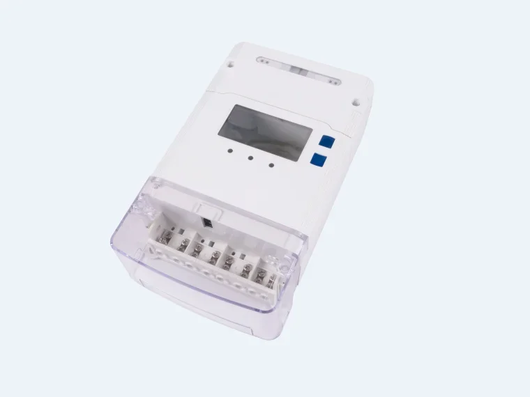
A three-phase electricity meter casing is the external enclosure that surrounds and protects the meter's internal electrical and electronic components. Depending on the application, it may be manufactured from engineering plastics, polycarbonate, ABS, or other specialized materials.
A typical three-phase meter enclosure may include several structural elements:
-
Main enclosure body
-
Front cover
-
Transparent or semi-transparent viewing window
-
Terminal cover
-
Mounting holes
-
Screw bosses
-
Cable entry openings
-
Sealing interfaces
-
Internal reinforcement structures
-
Locking or tamper-resistant features
The casing needs to balance several requirements. It must be strong enough to withstand mechanical loads while also providing dimensional stability, electrical insulation, weather resistance, and suitable protection against dust and moisture.
This makes the design of a three-phase electricity meter casing more complicated than simply creating a plastic box.
A casing can appear rigid and durable during normal inspection but still contain internal stresses or weak structural areas that gradually develop cracks after installation.
Why Is Cracking a Serious Problem?
Cracks in an electricity meter enclosure can have different consequences depending on their location.
A small crack on a non-structural surface may initially have limited impact. However, cracks around mounting holes, screw bosses, terminal areas, or sealing surfaces can become more serious.
For example, a crack around a screw hole can continue expanding when the fastener is tightened. A crack near a cable entry may compromise the enclosure's protective performance. A crack in a transparent meter window can affect visibility and, in severe cases, allow moisture or contaminants to enter.
For this reason, cracking should be treated as a potential indication of a deeper material, design, manufacturing, or installation issue rather than simply a surface defect.
Common Causes of Three-Phase Electricity Meter Casing Cracks
There are several major causes of cracking in a three-phase electricity meter casing. Identifying the actual cause requires looking at the crack location, shape, timing, environmental conditions, and manufacturing history.
1. Poor Material Selection
One of the most fundamental causes is inappropriate material selection.
Plastic materials have different levels of impact resistance, rigidity, thermal stability, chemical resistance, UV resistance, and environmental durability. A material that performs well in one application may not be suitable for another.
For example, a casing installed outdoors may experience:
-
High solar radiation
-
Large temperature variations
-
Rain and humidity
-
Salt-containing air
-
Dust
-
Industrial chemicals
If the selected plastic does not have sufficient environmental resistance, it may become brittle over time.
Material aging can reduce impact strength and elongation. As the material becomes less capable of absorbing stress, cracks are more likely to form around sharp corners, holes, or mounting points.
Solution: Select enclosure materials according to the actual operating environment. For outdoor three-phase electricity meter casings, manufacturers should consider UV resistance, temperature resistance, impact strength, chemical compatibility, and long-term aging performance rather than selecting material based solely on initial cost.
2. Internal Stress from Injection Molding
For many plastic meter enclosures, injection molding is a key manufacturing process. Although injection molding enables high-volume production with consistent dimensions, incorrect processing parameters can create residual stress inside the finished casing.
During molding, molten plastic flows into the mold cavity and then cools and solidifies. If different sections cool at different rates, internal stresses can remain in the molded component.
These stresses may not cause immediate cracking. Instead, the casing may remain intact after production but crack later when exposed to heat, chemicals, mechanical loads, or environmental changes.
Common processing factors include:
-
Injection pressure
-
Injection speed
-
Melt temperature
-
Mold temperature
-
Cooling time
-
Holding pressure
-
Holding time
-
Gate location
-
Material flow characteristics
Solution: Optimize the injection molding process and conduct appropriate process validation. Mold-flow analysis can also help identify areas where excessive flow stress, weld lines, or uneven filling may occur.
3. Excessive Stress Around Screw Holes
Screw holes are among the most common locations for cracks in a three-phase electricity meter casing.
When a screw is tightened, the surrounding plastic experiences compressive and tensile stresses. If the screw torque is excessive, the localized stress may exceed the material's strength.
The risk becomes greater when:
-
The screw diameter is too large
-
The hole diameter is too small
-
The boss wall is too thin
-
The screw is inserted at an angle
-
The fastening torque is too high
-
The boss lacks reinforcement
-
The plastic has become brittle
A crack may begin as a small line around the screw boss and gradually extend into the main enclosure.
Solution: Optimize screw-hole geometry and specify an appropriate fastening torque. Reinforcing ribs, better boss design, suitable hole dimensions, and controlled assembly procedures can significantly reduce this risk.
4. Sharp Corners Create Stress Concentration
Sharp corners can become weak points in a plastic enclosure.
When an external load is applied to a component with a sharp internal corner, stress tends to concentrate in that area. Instead of being distributed smoothly through the structure, the load becomes concentrated at a small location.
This can cause cracks to start at:
-
Internal corners
-
Mounting brackets
-
Rib intersections
-
Window openings
-
Cable openings
-
Screw bosses
The problem can become more noticeable after repeated mechanical or thermal loading.
Solution: Use appropriate radii rather than sharp internal corners. A well-designed three-phase electricity meter casing should distribute mechanical stress as evenly as possible. Rounded transitions between walls, ribs, and bosses can improve durability without necessarily adding substantial material.
5. Wall Thickness Is Too Thin or Uneven
Reducing wall thickness can lower material consumption and production costs, but excessive reduction may compromise structural reliability.
A casing with insufficient wall thickness may deform under mechanical loads or develop stress concentrations around openings and fasteners.
Uneven wall thickness can also create problems during injection molding because different sections cool at different rates. This may result in warpage, residual stress, sink marks, and dimensional instability.
Solution: Establish an appropriate and reasonably uniform wall-thickness design. Where additional strength is required, structural ribs can often provide reinforcement more efficiently than simply making the entire casing thicker.
6. Poor Mold Design
The mold has a direct influence on the quality of an injection-molded three-phase electricity meter casing.
Poor mold design can contribute to:
-
Uneven material flow
-
Weld lines
-
Air traps
-
Excessive residual stress
-
Incomplete filling
-
Local overheating
-
Uneven cooling
-
Dimensional variation
Weld lines are particularly important. When two material flow fronts meet, the resulting area may have lower mechanical strength than the surrounding material, depending on the material and molding conditions.
If a weld line occurs near a screw hole, corner, or mounting structure, it may become the starting point of a crack.
Solution: Optimize gate locations, runner systems, venting, cooling channels, and mold geometry. Mold-flow simulation can be useful before production tooling is finalized.
7. Temperature Changes and Thermal Cycling
Plastic expands when heated and contracts when cooled. Repeated temperature changes can therefore create mechanical stress in an electricity meter enclosure.
Consider a meter installed outdoors. During the day, the casing may be exposed to strong sunlight and heat. At night, temperatures can fall considerably. Seasonal temperature changes create an additional thermal cycle.
If the casing is assembled tightly against other components or constrained by mounting hardware, it may not be able to expand and contract freely.
Over time, repeated thermal cycling can contribute to fatigue and crack development.
Solution: Evaluate the thermal expansion characteristics of the selected material and consider the expected temperature range during product design. The casing should also allow reasonable dimensional movement without creating excessive constraint.
8. UV Exposure and Material Aging
Outdoor electricity meters can remain exposed to sunlight for years. Ultraviolet radiation can gradually degrade some plastics.
UV degradation may cause:
-
Surface discoloration
-
Loss of gloss
-
Brittleness
-
Reduced impact resistance
-
Surface microcracking
-
Reduced mechanical strength
A casing may therefore perform well during initial testing but become more susceptible to cracking after prolonged outdoor exposure.
This is especially important when the three-phase electricity meter casing is intended for long-term outdoor installation.
Solution: Use UV-resistant materials or appropriate UV stabilizers where required. Outdoor enclosure designs should be validated through suitable accelerated aging or weathering tests.
9. Chemical Exposure
Certain chemicals can weaken plastic materials or cause environmental stress cracking.
Potential sources include:
-
Cleaning agents
-
Oils
-
Solvents
-
Industrial chemicals
-
Adhesives
-
Lubricants
-
Certain plasticizers
The casing may initially look normal but develop fine cracks after repeated contact with a chemically incompatible substance.
This phenomenon is particularly important when mechanical stress already exists in the plastic.
Solution: Evaluate chemical compatibility between the enclosure material and substances that may contact the meter during manufacturing, installation, cleaning, or operation.
If a three-phase electricity meter casing will be used in an industrial environment, chemical exposure should be considered during material selection rather than after cracking occurs.
10. Impact During Transportation or Installation
Not every crack originates during manufacturing.
Electricity meters can experience mechanical shocks during transportation, storage, handling, or installation. A casing may be dropped, hit against another object, or compressed under excessive loads.
Some damage is immediately visible, while other impacts may create small internal defects that become visible later.
Improper installation can also create stress. For example, if the mounting surface is uneven and the installer forces the casing into position, the enclosure may become distorted.
Solution: Improve packaging protection, handling procedures, and installation instructions. Installers should avoid using excessive force and should ensure that mounting surfaces are reasonably stable and aligned.
11. Excessive Fastening Torque
Fasteners provide a secure connection, but more tightening does not necessarily mean better installation.
Excessive torque can generate significant stress around screw bosses. If the material is relatively brittle or the boss design is insufficiently reinforced, cracking may occur during installation.
Sometimes the crack appears immediately. In other cases, the damage develops gradually after repeated thermal cycling or vibration.
Solution: Define and control recommended fastening torque. Production assembly can use torque-controlled tools to improve consistency, while installation manuals should provide clear fastening requirements.
12. Material Reuse and Excessive Recycled Content
Recycled material can be valuable for reducing manufacturing waste and improving resource efficiency. However, its use must be carefully controlled for applications where mechanical reliability is important.
Repeated thermal processing can affect polymer properties, while contamination or inconsistent material composition may reduce performance.
If recycled content is used without adequate material control, batch-to-batch variation may increase.
Solution: Establish clear material specifications, control the percentage and quality of recycled content, and conduct mechanical and environmental validation on the final material formulation.
13. Design Changes Without Sufficient Validation
A seemingly small design modification can influence the mechanical performance of an enclosure.
For example, changing:
-
Wall thickness
-
Screw-hole diameter
-
Rib dimensions
-
Window size
-
Material grade
-
Gate location
-
Fastener type
may change stress distribution or molding behavior.
Cost-reduction projects can therefore unintentionally introduce new cracking risks.
Solution: Treat significant design and material changes as engineering changes that require appropriate verification. Prototype testing, dimensional inspection, impact testing, thermal cycling, and assembly validation can help identify problems before mass production.
Conclusion
A cracked three-phase electricity meter casing is rarely caused by a single issue. Material selection, injection molding conditions, structural design, screw fastening, thermal cycling, UV exposure, chemical contact, transportation, and installation can all influence the long-term reliability of the enclosure.
The most effective solution is therefore not simply to make the casing thicker or use more material. Instead, manufacturers should take a systematic approach that combines appropriate material selection, stress-conscious structural design, optimized molding parameters, controlled assembly, and application-specific testing.
For buyers, understanding these factors can make it easier to evaluate enclosure quality and identify a suitable three-phase electricity meter casing for different operating environments.
A well-designed casing should not only look good when it leaves the factory. It should maintain its mechanical integrity throughout installation, operation, maintenance, and long-term environmental exposure. By addressing potential cracking risks at the design and manufacturing stages, suppliers can improve product reliability, reduce field failures, and provide more durable protection for the electrical components inside the meter.
www.quan-sheng.net
quan-sheng